The wild eye
2007-05-28 19:10:25 UTC
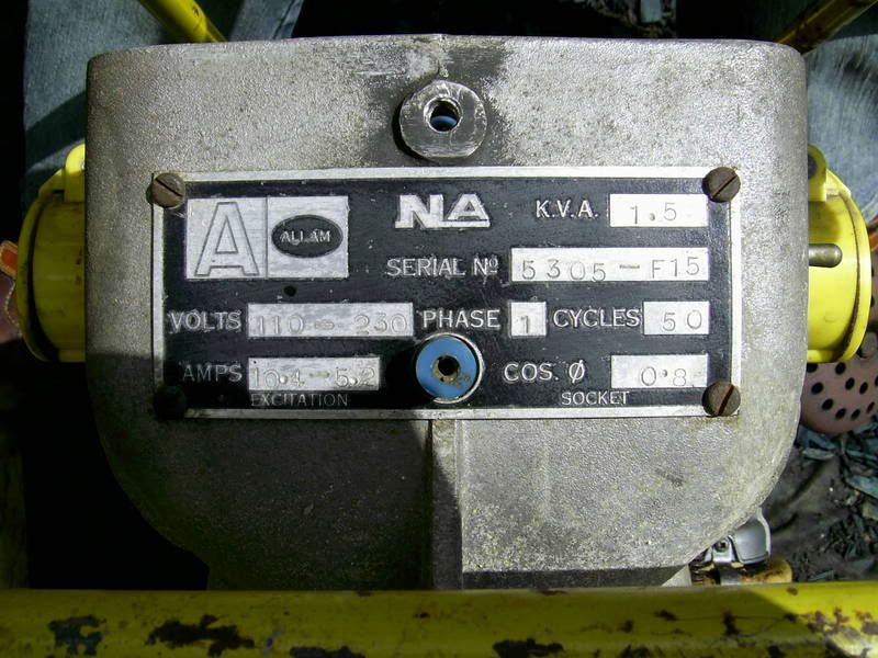
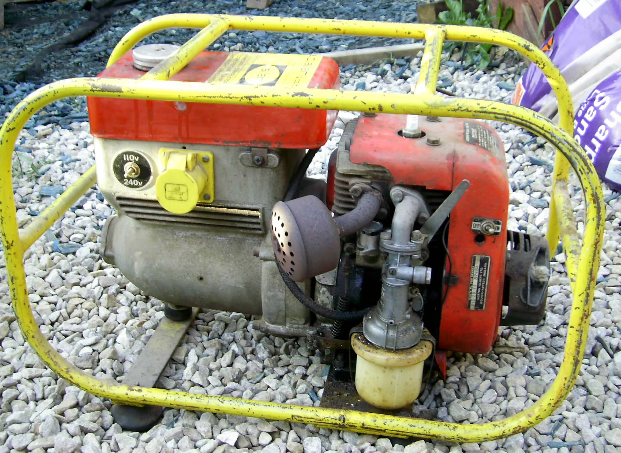
I have recently purchased a Minigen powered by a Villiers f15
Loading Image...
It runs well and puts out power .
but it will only give me 110 volts.
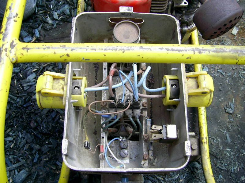
on inspection it appears that at some point somebody has bypassed the
switch that changes the voltage and rewired it to a permanent 110
has anybody any idea where I can find a wiring diagram so I can try
and put it right
Steve
Loading Image...
It runs well and puts out power .
but it will only give me 110 volts.
on inspection it appears that at some point somebody has bypassed the
switch that changes the voltage and rewired it to a permanent 110
has anybody any idea where I can find a wiring diagram so I can try
and put it right
Steve